I’m a “tech” guy and one of the fears I had about buying a radio from the late 80’s to early 90’s was that I would not be able to connect it to the computer. Before buying my Kenwood TS-440SAT I did some research and found out that by installing an IC-10 Kit, which consists of 2 separate IC’s that you just plug into the open spaces on the board, the radio becomes capable of interfacing with a computer.
The other required parts to complete the connection are:
- Kenwood IF-232C – This is a TTL to serial converter that will take the TTL signal from the radio’s ACC 1 connection port and translate it to RS232 serial for the computer to understand. It also does the reverse for communication the other way.
- Cables to connect the radio’s ACC 1 port to the IF-232C and another to connect the serial port on the IF-232C to the computer.
After reviewing the price for these pieces, roughly $40+ assuming I could find a used IF-232C somewhere and it was in working condition, I decided that I would look into the usb to 6 pin din cables that are all over ebay… unfortunately these were also about $35+.
I did some research and determined that buying one of these cables is really a crapshoot as to whether or not the computer will recognize it or even whether it will be functional at all. I did discover that the recommended cables are the ones that is based off the ft232rl (FTDI) chipset. Turns out I happened to have a $6.00 FTDI programmer so I thought I would attempt to make my own cable and after some trial and error, it is now working.
So … Why buy a $35+ cable when you can make your own for less than $15! Follow the below instructions to build your own.
Tool List:
- Soldering Iron, Solder and Flux
- Wire Stripper / Cutter
- Download FT_PROG to program your FTDI
Parts list:
- 5V FTDI Programmer
(cheapest on Ebay at about $3.50 if you have patience to order from China, or $8 on Amazon and get it sooner) - 6 Pin Din Connector about $5-6 on Amazon
- Small length of phone cord
- A mini usb cable to connect the FTDI to the computer (if you don’t already have one for some strange reason, they are about $1-3 on amazon, even less at a thrift store)


Steps:
- Connect your FTDI to your computers USB port
a) Install and launch FT_PROG
b) Click “Devices”->”Scan and Parse”
c) Click the “+” next to “Hardware Specific”
d) Click “Invert RS232 Signals
e) in the box on the top right check the following boxes: Invert TXD, Invert RXD, Invert RTS#, Invert CTS#
f) Click “Devices” -> “Program”
g) After completed unplug your FTDI from your computer - Cut a 12″ length of phone cord that will be used to connect the 6 pin din connector to the FTDI programmer and strip the ends of the sleeve back about an inch and a half and then strip the wires each about one half inch.
- Slide one end of the phone cord through the rubber fitting for the DIN Connector
- Use the following Diagrams to solder the phone wires to the pins on the back side of the DIN connector and solder the respective colored wire to the correct pin on the FTDI

NOTE! Your FTDI may not have a pin marked “RTS”, “RTS” is the same as “DTR”. Pin 6 on the DIN and VCC on the FTDI are not connected. - Slide the rubber jacket onto the DIN connector and use some heat shrink tubing on the FTDI if you want.
- Plugin and go!
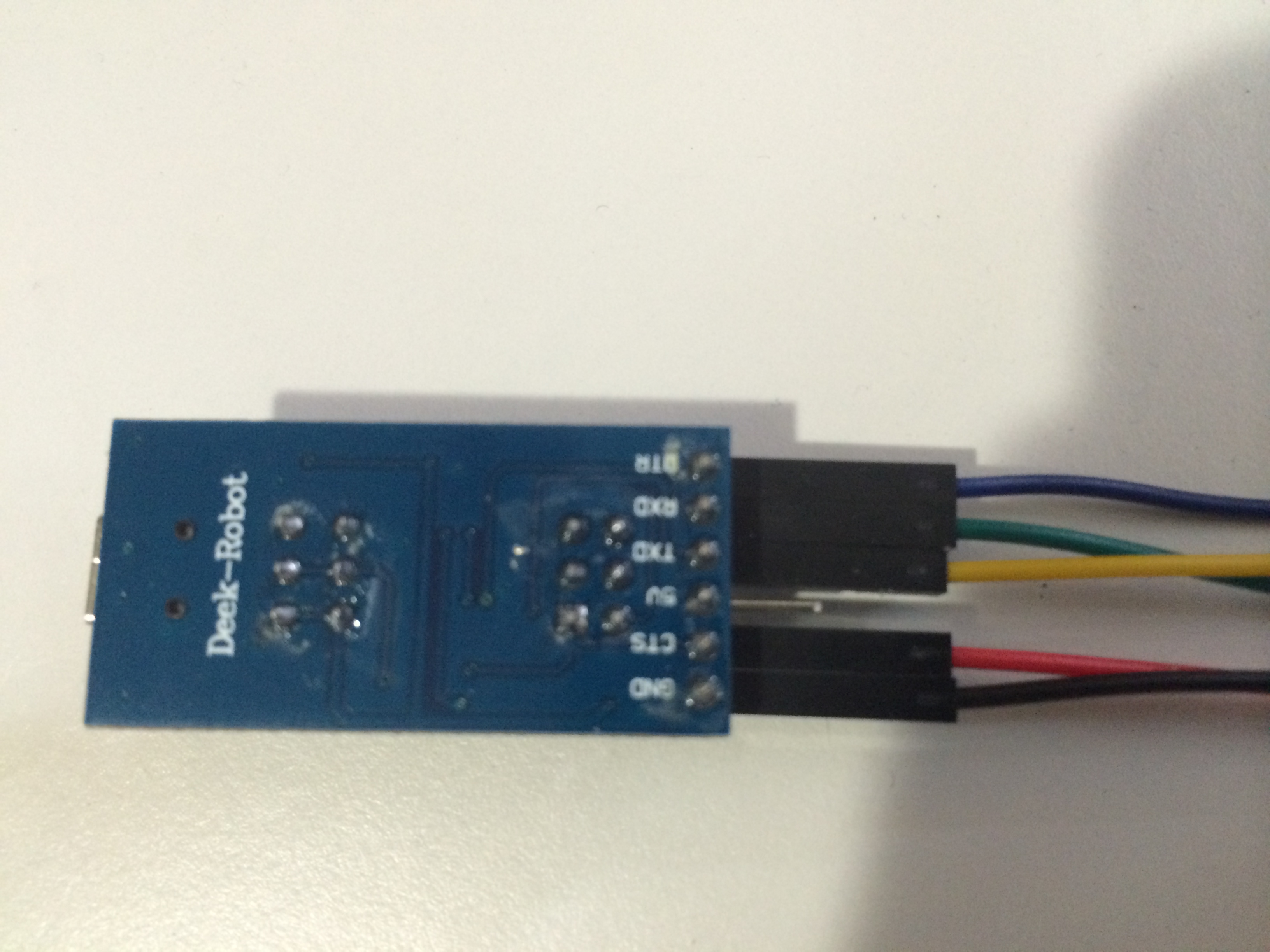
Here is a picture of my wiring, however I was using colored jumper wires at this point and not the phone cord.


The following screen shots show the settings I am using with DXLabs Suite to control the radio.


If you have any questions or improvements let me know!
73’s KE0BMA